Home heat pump heating system design scheme
I. Entrance Hall/Living Room Electric Underfloor Heating System Solution
The entrance hall is the corridor into the home, and the feeling of home should begin here. The living room is an important area for family activities, entertainment, and entertaining guests. Maintaining a comfortable environment in the living room will make us feel more joyful.
II. Kitchen/Dining Room Heating System
Comfortable moments in the kitchen, enjoying breakfast with family on winter mornings, making life feel better.
III. Bedroom Heating System
Warm happiness, making you fall in love with the feeling of winter flowers blooming, making life more warm, comfortable, and happy.
IV. Children's Room Heating System
Let children say goodbye to layers of bulky winter clothes during the cold season, freely and happily enjoying a joyful childhood and growing healthily.
V. Study Heating System
Enjoy a quiet space for reading in a modern home, a secluded valley for cultivating character and self-discipline, while teaching children how to read and learn. Satisfying children's interests and thirst for knowledge
VI. Bathroom/Toilet Heating System
The choice of five-star hotels worldwide, providing the feeling of unrestricted foot contact with the floor while bathing, drying the damp floor after showering for better hygiene, and preventing bacterial growth and odors. An ideal bathroom heating system solution.
What factors should be considered in the design of an underfloor heating system?
I. Heat Dissipation Calculation
1. Heat Load: For vertically adjacent rooms, except for the top floor, the actual heat load required by each room should be determined by deducting the heat flowing from the upper floor from the room's heating load. This applies to centralized heating (in the "Technical Specification for Radiant Cooling and Heating,"
when the average water supply temperature is 45℃, there is heat dissipation from the floor itself, as well as downward heat dissipation). Typically, the heat load of insulated housing is 70-90 watts per square meter, while that of uninsulated housing is 100-110 watts per square meter.
The heat load per unit area varies depending on the insulation performance of buildings in different regions (for example, in Chengdu, where housing insulation is poor and winter humidity is relatively high, the heat load per unit area needs to be designed to be 110-130 watts per square meter).
2. Heating Time: When calculating the heat load per unit area for both centralized and individual heating systems, users need to consider factors such as intermittent heating and heat transfer between rooms when adjacent rooms are not heated. Appropriate correction coefficients should be adjusted to determine the actual heat load value for each room.
3. Floor Obstructions: Underfloor heating design should consider floor coverage. For example, custom-made cabinets, legless sofas, legless beds, tatami mats, etc., may obstruct the floor. The impact of furniture obstruction on heat dissipation should be considered, as heat still escapes even where furniture is blocking it. Floor obstructions reduce the effective heat dissipation area,
thus increasing the heat load per unit area of the room. Different types of furniture have different impacts, and underfloor heating also affects furniture materials; solid wood furniture is easily warped by the heat.
II. Underfloor Heating Pipe Circuit Design
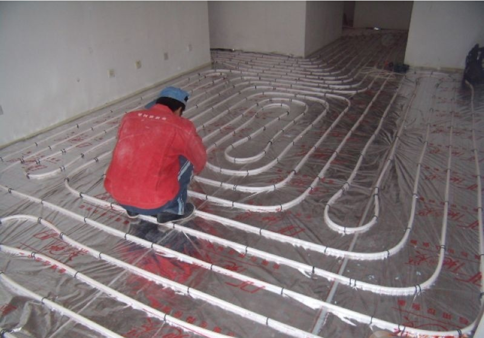
1. Underfloor Heating Circuit Division: Each underfloor heating pipe circuit area should be rationally divided, aiming for independent control per room and avoiding intersections with other pipes. If the room area is large, two or more circuits can be used to supply one room. Adjacent rooms should not share the same circuit. 1. **Important Notes:** Underfloor heating pipes should be laid without joints.
If a pipe is damaged, the entire circuit can be re-laid. If re-laying is not possible, a reliable connection method should be used, and a pressure test must be performed. Heating can only resume after confirming there are no leaks.
2. **Number of Manifold Circuits:** Underfloor heating circuits connected by the same manifold should have consistent pipe lengths to avoid differences in system resistance, uneven heating/cooling, and material waste.
3. **Expansion Joint and Wall Insulation Strip Design:** When the underfloor heating area exceeds 30 square meters or the side length exceeds 6 meters, expansion joints should be installed within 6 meters. The width of the expansion joint should not be less than 8mm to mitigate the thermal expansion caused by the underfloor heating system.
Side insulation layers (wall insulation strips) should be installed at junctions with interior and exterior walls, thresholds, columns, etc., to reduce heat loss and alleviate expansion pressure. 20mm thick polyethylene foam boards can be used, with no gaps at the joints; a 10mm overlap is acceptable.
4. Prevention of Backfill Cracking: After the underfloor heating system is installed, cement mortar backfilling and leveling are required. To prevent cracking, a layer of wire mesh or nylon mesh should be added during backfilling.
When designing underfloor heating parameters, the temperature, water volume, and pressure difference of the underfloor heating and water supply/return systems should be matched. The supply water temperature should be less than 60℃, the supply and return water temperature difference should be less than 10℃, and the system working pressure should not exceed 0.8MPa (for radiator water supply temperatures between 70℃ and 80℃,
the supply and return water temperature difference should be less than 20℃). The flow velocity of circulating water in the underfloor heating system should not be less than 0.25m/s to reduce airlock.
Manifolds come in various sizes, such as Dn20mm, Dn25mm, and Dn32mm, with a maximum cross-sectional flow velocity not exceeding 0.8m/s. Each manifold should not have more than 8 loops, and each loop should be equipped with an independent on/off valve. On the water supply connection pipe before the distributor, a shut-off regulating valve, a filter, and a drain valve should be installed in the direction of water flow.
On the return water connection pipe after the collector, a drain valve should be installed and a balancing valve or a shut-off regulating valve should be added.

